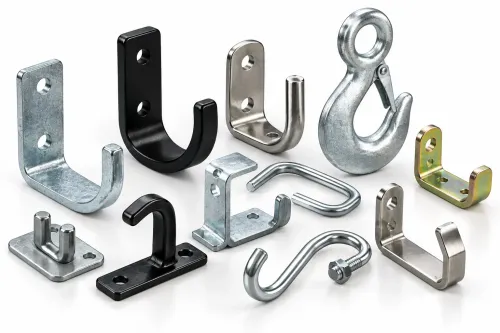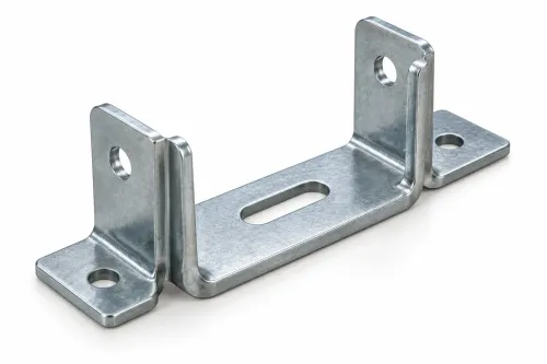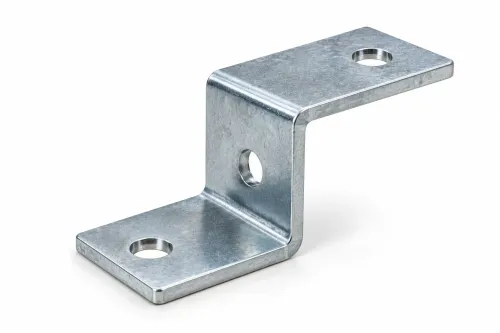
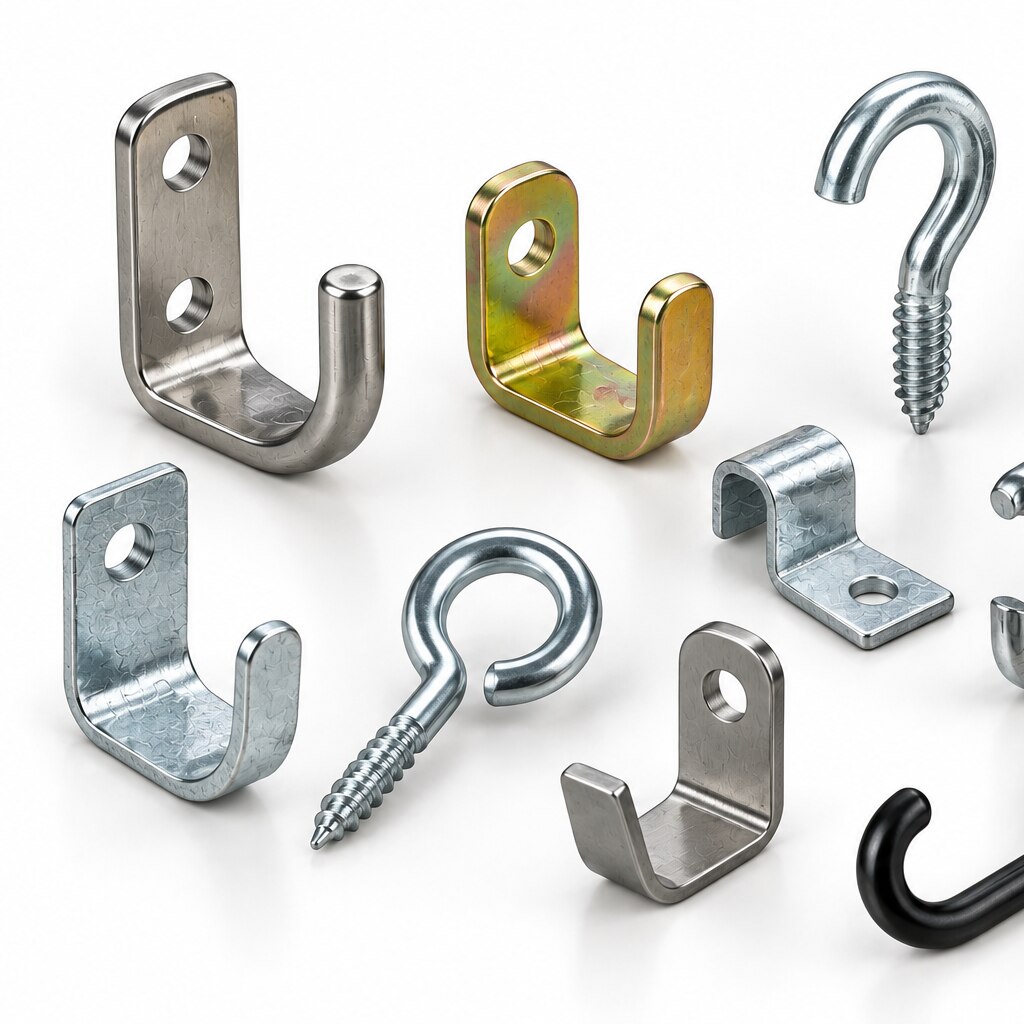
A small hook can hold a spring, retain a panel, guide a cable or connect two parts, but the wrong opening, bend radius or load direction can cause jamming, disengagement or fatigue failure. Use the guidance below to choose the hook geometry, dimensions, material, finish and manufacturing method, then define checks that prove it will work in your assembly.
Key takeaways
- Use open hooks for side access and closed-eye hooks for captive joints.
- Define throat, opening, wire diameter and insertion clearance before ordering.
- Rate hooks for load direction, repeated cycling and a stated safety margin.
- Specify material, finish, manufacturing route and measurable acceptance checks.
Match the Hook Geometry to the Assembly Job
Choose the hook by matching its entry path and retention to the assembly: side access favours an open hook, while a captive joint needs a closed-eye hook and a defined insertion sequence.
| Geometry | Access and retention | Best assembly use |
|---|---|---|
| Open hook | Fast side entry; easiest to disengage | Removable covers, temporary fixtures and parts that need tool-free installation |
| J-hook | Enters over a pin from one direction; resists pullout along the hook axis | Tension springs, latches and edge-mounted retainers |
| S-hook | Links two eyes or wires while allowing adjustment | Hanging components, flexible linkages and assemblies requiring two-sided access |
| Closed-eye hook | Captive after installation; needs an end-over-end path or a mating part installed first | Permanent spring-to-pin connections and restrained tension members |
| Crossover or latch-style hook | Improves retention where vibration could open a simple hook | Moving assemblies, retaining clips and connections exposed to repeated motion |
Use an open hook only when accidental release is controlled by load direction, a guard or a secondary retainer. A closed-eye hook prevents disengagement but can make assembly impossible after the mating pin is fixed.
For oil-seal garter springs, select the end connection with the seal installed. Hook-and-eye, butt-hook and connector joints change circumferential tension, radial protrusion and elastomer loading; free spring length alone cannot reveal those effects.
Control hook angle and position as functional dimensions, because variation can increase installation torque, shift the load sideways or change the working force.
Specify the Functional Dimensions and Check the Fit
Approve a hook for production only after comparing its functional dimensions with the mating part’s worst-case envelope, not just nominal drawing values. Measure wire diameter, outside width, inside opening, overall length, bend radius, leg length, hook throat depth, end orientation, hook angle, hook position and coil diameter.
A fit that works at nominal size can jam when coating thickness, mating-part tolerance, hook ovality, angular misalignment or movement consumes the clearance.
| Dimension | Compare against | Why it matters |
|---|---|---|
| Wire diameter | Drawing value and supplier tolerance | Changes strength, coil diameter and forming geometry |
| Outside width | Available assembly space | Prevents interference with guides, housings or adjacent parts |
| Inside opening | Maximum mating-part envelope | Provides entry without forcing the hook open |
| Overall length | Installed length and working position | Affects spring force and engagement depth |
| Hook angle and position | Assembly axis and reference datum | Controls installation torque, side preload and installed length |
| Throat depth and end orientation | Retention feature and access path | Prevents shallow seating or accidental release |
Use the maximum pin or wire size, coating and angular error to establish the mating envelope. Then confirm that the minimum inside opening still engages freely; excessive clearance can permit disengagement or impact loading.
- Request minimum and maximum opening, angle, free length and coil diameter.
- Test a physical sample through the full assembly path, including seating and removal.
- Record force at each specified deflection with seating condition, temperature and loading rate; a force value without those conditions cannot be compared reliably.
Check Load Direction, Fatigue and Safety Limits
A hook suitable for a static load can still fail after a few thousand cycles. Treat the hook as a fatigue-critical termination: the highest stress usually occurs where the coil or shank transitions into the hook, and a tight bend radius, short leg length or shallow hook throat depth increases local bending stress.
Match the hook to the actual load case:
- Static load: verify force at the specified working deflection and check that the hook does not open or take a permanent set.
- Shock load: allow for the impact peak, not just the part’s weight. A hook that safely holds a suspended component can deform when that component stops suddenly.
- Repeated cycling: require fatigue evidence or a representative endurance test. A proof-load test finds gross forming defects, wrong material and permanent deformation; it does not prove fatigue life.
- Side loading: define the load line, hook plane and allowable rotation on the assembly drawing. Loading outside the intended plane adds bending and torsion, often causing early failure at the hook transition.
- Prying or lifting: do not rate a retaining hook for lifting unless the design and test specifically cover it. Prying can force the opening apart even when axial force remains below the static load.
Production checks should measure force at defined deflections, then inspect hook opening, hook angle, free length, coil diameter and permanent set. Record the seating condition, temperature and loading rate; a force value without those details cannot be compared reliably.
Choose Material and Finish for the Service Environment
An uncoated spring wire can meet the load requirement and still fail from rust, hydrogen embrittlement or stress relaxation. Select the steel and finish together, then verify that the chosen wire can be formed without cracking or losing its required spring force.
| Material and finish | Strengths | Limits and checks |
|---|---|---|
| Carbon steel, zinc-plated | Low cost and easy forming; suitable for dry indoor assemblies | Zinc damage at bends exposes steel. Specify pretreatment, plating thickness and corrosion acceptance. |
| Spring steel, such as ASTM A228/A228M music wire | High tensile strength and strong spring performance | Poor inherent corrosion resistance. Avoid acid cleaning or electroplating without a controlled hydrogen-embrittlement process and applicable post-plating relief. |
| Stainless steel spring wire to ASTM A313/A313M | Better corrosion resistance for humid, washed or mildly chemical environments | Choose the grade for strength, magnetic response, temperature and stress relaxation; do not substitute it without checking the design. |
| Galvanized steel | Useful where sacrificial zinc protection is needed | Forming can fracture the coating, and high temperature can reduce protection. Inspect cut ends and tight bends. |
Specify the service temperature, humidity, chemicals, contact metals and forming radius on the drawing. A tight bend in high-strength spring steel needs controlled tooling; forcing it after plating can split the finish. For zinc or nickel plating, require documented pretreatment, process controls and delayed-fracture acceptance—not just the coating name.
Use ASTM B117 or ISO 9227 salt-spray results to compare finishes, not to predict field life. Scribe condition, deposits, wet-dry cycling and Pune’s actual environment can change the outcome.
Select the Manufacturing Route and Define Acceptance Checks
Use a formed-wire hook when the assembly needs a smooth, continuous load path, rounded contact, or a three-dimensional bend that must engage a pin without a sharp stamped edge. Choose a stamped sheet-metal hook for flat profiles, broad bearing surfaces and high-volume repeatability; choose a laser-cut hook for prototypes, low volumes or rapid profile changes.
| Route | Best fit | Main risk to control |
|---|---|---|
| Formed wire hook | Pins, springs, retainers and 3D access paths | Hook angle, coil diameter and bend repeatability |
| Stamped sheet-metal hook | Flat hooks with wide contact or mounting faces | Burrs, edge radius and springback |
| Laser-cut hook | Prototypes and complex flat outlines | Heat-affected edges, burrs and slower production cost |
For automated assembly, request the actual functional envelope rather than a nominal drawing. The supplier’s data should state minimum and maximum hook opening, hook angle, free length, coil diameter, force at each specified deflection, test temperature, loading rate, seating condition and the gauge or go/no-go method.
- Measure hook opening, free length, hook angle and coil diameter on production samples.
- Record force at defined working deflections, then inspect permanent set after loading.
- Apply a proof load to expose wrong material, gross forming defects and permanent deformation; do not treat it as fatigue-life evidence.
- Check hook position against the load line and inspect burrs, edge radius and contact width at the mating pin or slot.
Shankar Spring And Coil Works should provide batch-level dimensional and force records so you can distinguish a controlled process from parts that merely passed visual inspection.
Related product
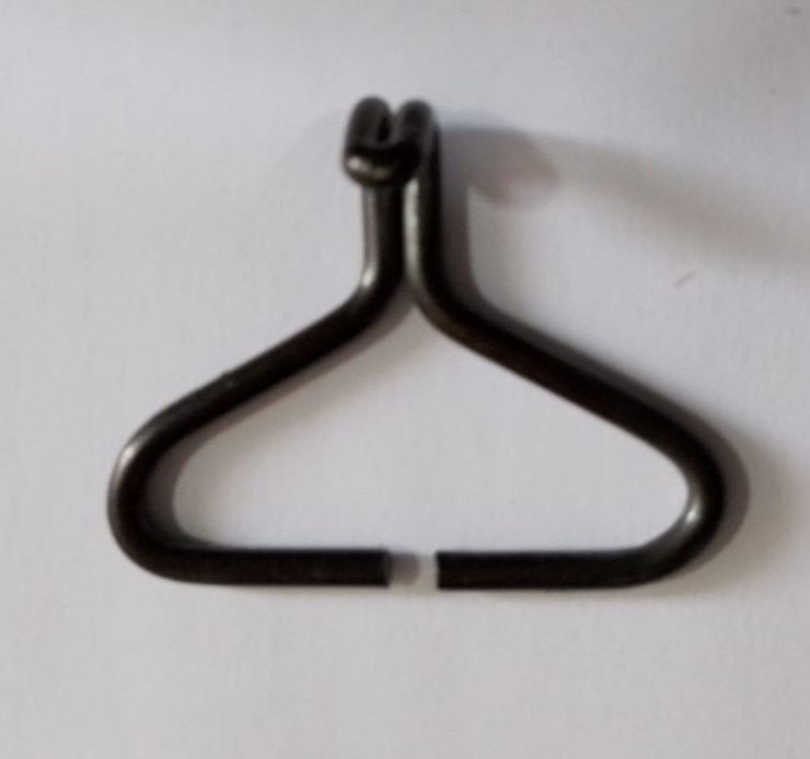 | Small Hook Small Hook View product → |
Frequently asked questions
How do I choose the right hook geometry for an assembly?
Match the geometry to the entry path and retention need: use an open hook for side access and a closed-eye hook for a captive joint.
Which hook dimensions should I specify?
Specify wire diameter, overall length, hook opening, throat depth, eye dimensions and assembly clearance, then check the fit on the mating parts.
How should I assess a hook’s load capacity?
Check the load direction, peak load, repeated cycling and safety margin; do not rate a hook from static pull alone when the assembly vibrates or flexes.
How do material and finish affect hook selection?
Choose the material and finish for corrosion, temperature, wear and forming requirements in the service environment.
What acceptance checks belong on a hook order?
Define dimensional tolerances, opening and orientation limits, surface defects, finish requirements and a sampling or inspection plan before production.