A backup ring cannot be judged by its nominal O-ring size or a standalone pressure claim. You need to test the proposed design against the actual gland, pressure direction, movement, temperature, fluid, tolerances and evidence of production control before approving a manufacturer.
Key takeaways
- Match ring geometry to pressure direction and seal motion.
- Confirm groove dimensions, clearances and ring orientation before approval.
- Demand material grades, test data and traceable inspection records.
- Compare suppliers on process control, not samples alone.
What a backup ring must do in the seal assembly
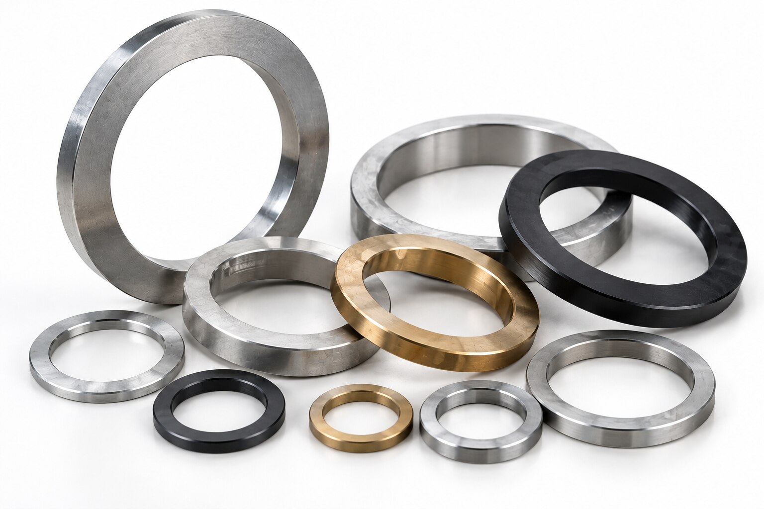
A backup ring prevents O-ring extrusion by supporting the elastomer against the clearance gap behind the gland. Pressure pushes the O-ring into that gap; the ring occupies the space and limits deformation, nibbling and eventual seal failure in high-pressure service.
Check the anti-extrusion gap at the actual operating condition, not only on a room-temperature drawing. Include:
- Maximum pressure and temperature
- Shaft-to-bore misalignment and eccentricity
- Hardware tolerances and thermal expansion
- Pressure cycling and the direction of pressure
Specify the backup ring with the O-ring, gland geometry, fluid, temperature and pressure direction. Its pressure rating is not an independent catalogue value: clearance, ring hardness, orientation and O-ring deformation can control performance. ISO 3601 defines metric O-ring dimensions and tolerances, but does not qualify a backup-ring assembly for a particular application.
Use a backup ring when the validated clearance permits extrusion and the existing seal profile or hardware cannot provide enough support. Choose a redesigned gland or seal profile when changing the geometry will close the gap more reliably.
Omit the ring when the gap and operating limits already fall within validated O-ring performance; adding one can create installation damage, friction or an incorrect gland fill.
Which backup-ring design matches the motion and pressure direction
Match the joint and stiffness to the pressure side and motion: a solid backup ring suits many static glands, while dynamic service demands evidence that the joint will not wear, open or become an extrusion path.
| Option | Static service | Reciprocating service | Rotary service |
|---|---|---|---|
| solid backup ring | Best continuity and extrusion resistance; requires installation access and correct thermal clearance. | Use only after stroke and wear testing; a rigid ring can damage the seal if the gland is wrong. | Consider only with a purpose-designed gland, low friction and controlled runout. |
| split backup ring | Easy installation, but the split must not face the pressure side. | Acceptable only with defined split geometry, orientation and cycle testing. | Usually risky because the joint can catch, wear or mark the sealing surface. |
| scarf cut | Easier assembly than a solid ring, with a diagonal joint that limits a straight extrusion path. | Suitable when the scarf angle, overlap and wear results are documented. | Require rotary testing; joint movement can still generate friction or damage. |
| step cut | Interlocking joint improves resistance to extrusion and joint opening. | Useful for demanding motion when step engagement survives the specified cycles. | Use only with confirmed step alignment and rotational clearance. |
| spiral backup ring | Continuous support with installation trade-offs. | Consider for dynamic sealing after representative testing. | Potentially suitable, but verify winding direction, friction and pressure orientation. |
Require drawings showing joint geometry, overlap or gap, installation direction and pressure side. Test reciprocating rings at the actual stroke, speed, pressure, temperature, lubricant and cycle count; static leakage alone proves little.
How to choose the ring material and grade
Specify the material grade against pressure, temperature, fluid, wear and movement—not simply “PTFE” or “plastic.” The correct choice also depends on the extrusion gap, O-ring hardness, gland geometry and pressure direction, so a catalogue pressure rating without those conditions is unusable.
| Material | Strengths | Specify when | Main risk |
|---|---|---|---|
| PTFE | Low friction and broad chemical resistance | Static or low-speed service with demanding fluid compatibility | Virgin PTFE creeps under sustained pressure and can extrude |
| Filled PTFE | Better creep and deformation resistance than virgin PTFE | High-pressure service requiring lower friction than engineering polymers | Glass, carbon or bronze fillers can increase shaft wear or react with the fluid |
| PEEK | High temperature capability, stiffness and wear resistance | High-pressure, reciprocating or abrasive service where dimensional stability matters | Higher friction and chemical limits than PTFE; verify the specific compound |
| Polyurethane | Excellent abrasion, tear and nibbling resistance | Dynamic seals with shaft movement and repeated cycling | Temperature, hydrolysis and chemical resistance depend strongly on grade |
For reciprocating service, qualify the selected grade at the actual stroke, speed, pressure, temperature, lubricant and cycle count. Inspect the backup ring and O-ring for wear, nibbling and joint damage; a static leakage pass proves little.
Put the resin or compound designation, filler content, hardness where relevant, temperature range and fluid exposure on the purchase specification. Treat any proposed substitute as a controlled change: compare mechanical properties, chemical compatibility, ageing, friction, wear and assembly performance before approval.
How to prove the ring fits the existing gland
A nominal O-ring match proves almost nothing about fit. Confirm the installed gland, hardware limits and seal deformation at maximum pressure and temperature, not only against room-temperature drawing dimensions.
- Measure the actual shaft diameter and bore diameter, then calculate the radial clearance around the O-ring. Include shaft-to-bore misalignment and eccentricity; these can enlarge the extrusion gap on one side.
- Record the O-ring cross-section, inside diameter, hardness and material grade. Check that the proposed ring leaves enough gland volume for thermal expansion and pressure-driven deformation without creating excessive compression or friction.
- Verify groove dimensions: width, depth, corner radii, side clearances and surface finish. Confirm the backup ring’s axial thickness, radial height, joint type and orientation against those dimensions.
- Apply the full tolerance stack, including shaft, bore, groove and ring tolerances. Recheck the effective anti-extrusion gap through pressure cycling and thermal expansion.
| Check | Evidence to request | Failure if missed |
|---|---|---|
| Nominal seal size | O-ring cross-section and ISO 3601 designation | Ring fits the seal but not the gland |
| Hardware geometry | Measured shaft, bore and groove dimensions | Local extrusion or binding |
| Operating stack | Maximum pressure, temperature and misalignment calculation | Room-temperature inspection passes, service fails |
| Assembly | Trial fit and joint inspection | Split or step catches the elastomer |
ISO 3601 identifies O-ring dimensions; it does not prove this assembly works. Require the supplier to document the separate gland, material and test criteria used.
Which performance figures and qualification tests to demand
Accept a backup ring only when its rating is tied to your seal, gland and fluid. A quoted maximum pressure is incomplete unless the supplier states ring material and hardness, pressure direction, temperature range, O-ring compound, gland clearance and hardware tolerances.
The permissible extrusion gap must be checked at the actual temperature and pressure, not only at room-temperature nominal dimensions.
Request these figures on the drawing or datasheet:
- Maximum pressure at the specified extrusion gap, including pressure cycling conditions.
- Temperature range in the actual fluid, with separate continuous and peak limits.
- Permissible extrusion gap across the full tolerance stack, including eccentricity and thermal expansion.
- Sliding speed, stroke length and pressure limit for reciprocating service.
- Split geometry, installation orientation and joint gap for split, scarf-cut or spiral rings.
- ISO 3601 part and designation for the O-ring, plus the separate material and gland criteria used.
| Evidence | What to demand | Reject if |
|---|---|---|
| Static pressure test | Pressure, temperature, fluid, dwell time and leakage limit | Only a pressure number is supplied |
| Dynamic qualification | Representative stroke, sliding speed, cycles and lubricant; inspect both rings after testing | A static test stands in for reciprocating service |
| Dimensional validation | Recorded ring dimensions, tolerances and installed gap at tolerance extremes | The sample matches nominal size only |
For production acceptance, require test reports identifying specimens, conditioning, failure definition and photographs of wear, nibbling, joint damage or extrusion. A certificate without these details is not qualification evidence.
How to assess manufacturing control and supplier evidence
A catalogue number and material certificate do not prove repeatable production. Ask the supplier to connect the approved drawing, ring orientation, material grade, tolerances and application conditions to a controlled process, then show records from multiple production batches rather than one attractive sample.
1. Request a drawing-ballooned inspection plan listing every critical dimension, split or scarf geometry, burr limit, hardness and surface condition. Compare the listed results with specification limits, not nominal values alone.
2. Check batch traceability from incoming PTFE, PEEK or other stock through machining, forming, heat treatment and final inspection. The material certificate must identify the resin or compound designation, filler content where applicable, and actual batch number.
3. For automotive or tier-one work, demand a complete PPAP: process flow, PFMEA, control plan, dimensional results, material and performance records, measurement-system evidence and capability data for special characteristics. A certificate of conformity is not PPAP.
4. Treat Cpk cautiously unless the supplier provides stable control charts, subgrouping, specification limits and gauge-capability results. A short, selected sample can produce a convincing number without proving control.
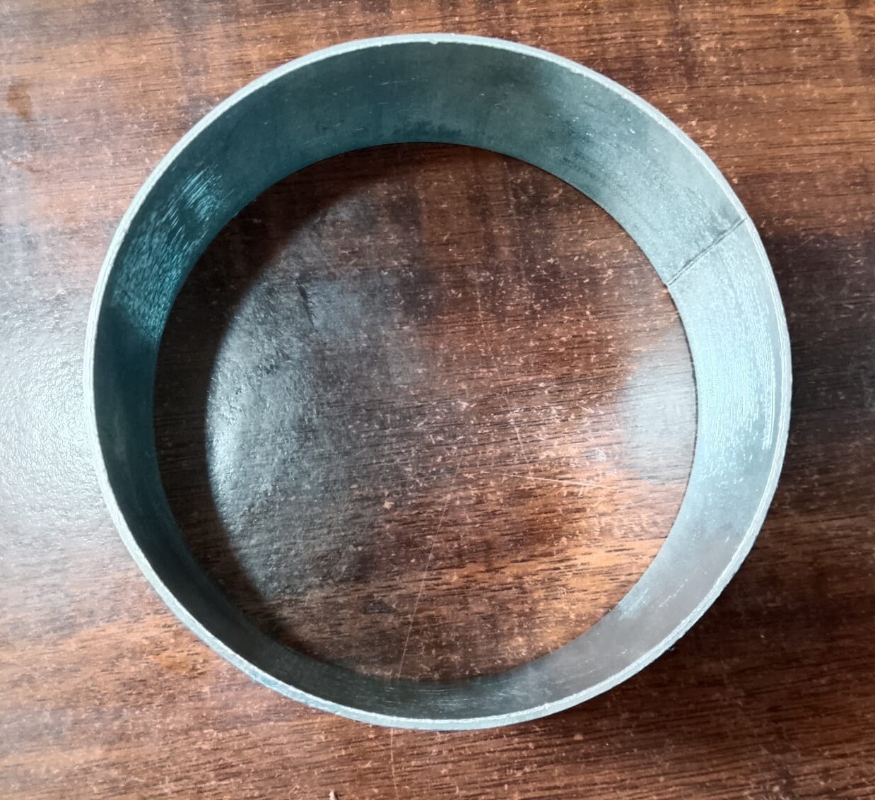
Ask Shankar Spring And Coil Works for these records before treating its backup-ring listing as manufacturing evidence; the same test separates a controlled custom supplier from a catalogue reseller. Reject any rating that gives only maximum pressure without gland clearance, seal hardness, pressure direction and temperature.
Related product
 | Backup Ring Backup Ring View product → |
Frequently asked questions
What does a backup ring do in an industrial seal assembly?
It supports the O-ring against the clearance gap, limiting extrusion, nibbling and pressure-related seal failure.
How do you choose the right backup-ring design?
Match the ring’s geometry and split pattern to the pressure direction, reciprocating or rotary motion, and gland arrangement.
How do you select a backup-ring material and grade?
Compare temperature range, pressure, fluid compatibility, wear resistance and the exact material grade against the application conditions.
How can you prove a backup ring fits an existing gland?
Measure the gland width, depth, diameter, clearance and O-ring dimensions, then verify orientation and assembly without pinching.
What evidence should a backup-ring manufacturer provide?
Request dimensional inspection results, material certificates, performance or qualification test records, batch traceability and documented process controls.