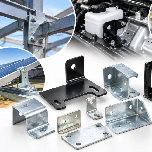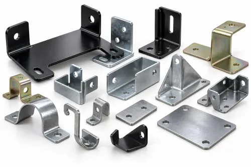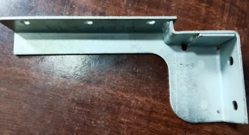
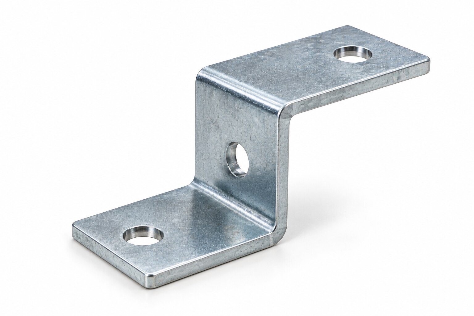
A Z bracket is defined by its offset and formed mounting faces, so choosing one by a catalogue name alone can produce hole misalignment, excess bending load, or poor clearance. By the end, you will be able to read the required geometry, check the working load and mating parts, compare materials and alternatives, and assess whether a manufacturer can produce the bracket consistently.
Key takeaways
- Specify both mounting faces, offset, hole pattern, bend radii, and tolerances.
- Calculate working load from bracket orientation, fasteners, material, and safety factor.
- Match material thickness and finish to corrosion, strength, and forming requirements.
- Request samples, inspection records, and dimensional evidence before approving production.
What Makes a Z Bracket Different from Other Mounting Parts?
A Z bracket’s geometry creates two mounting faces separated by an offset, so it connects misaligned planes while holding a component clear of its support. Its bends form a stepped load path rather than the single corner of an angle bracket.
| Part | Geometry | Practical effect |
|---|---|---|
| L bracket | One 90-degree bend joining two perpendicular faces | Suits a corner connection, but offers little controlled spacing between the faces |
| Flat plate | One planar mounting surface with holes | Fast and simple, but cannot bridge a gap or create a raised mounting position without spacers |
| Strap | Narrow strip formed around or across a component | Holds or restrains parts, but provides less broad mounting area and directional stability |
| U bracket | Two opposing sides joined by a base | Captures or supports a part inside a channel; access and insertion space become design limits |
| Gusseted bracket | Main angle reinforced with a triangular plate | Resists corner deflection well, but adds material, clearance demands, and fabrication |
| Fabricated plate | Cut, bent, welded, or assembled plate sections | Handles complex loads and shapes, but introduces more joints, tolerances, and inspection points |
The offset determines clearance, lever arm, and bending stress. A larger offset can clear a tank wall or frame flange, but it also increases the moment transferred through the bends and fasteners.
Hole patterns on separate mounting faces let you fix the bracket to two planes without a spacer. Check that the bends leave tool access and that the final mounting faces remain parallel or perpendicular as the assembly requires.
A Z bracket is the wrong choice when a flat, direct load path is stronger and the offset serves no functional purpose.
How to Turn a Drawing into a Production-Ready Z Bracket Specification
Give the fabricator the formed part’s overall length, width, height, and offset dimensions from named datums, not from an unspecified edge. State each bend angle, inside bend radius, bend direction, and the faces that must remain parallel or square.
- Mark the primary datum on the functional mounting face, the secondary datum on its perpendicular face, and the tertiary datum from a locating edge or hole.
- Dimension every hole from those datums: diameter, centre position, hole-to-hole spacing, slot length and width, end radii, countersink or counterbore, and positional tolerance.
- Specify linear, angular, flatness, perpendicularity, and parallelism tolerances for the mounting interfaces. ISO 2768 covers unspecified dimensions; it does not define the hole position or bend-to-hole accuracy your assembly may need.
- State material grade, temper or condition, nominal thickness and thickness tolerance, grain direction where bending could crack the part, and whether holes are punched, laser-cut, or drilled.
- Add deburring limits, allowable edge condition, surface finish, coating process and thickness, post-treatment, and any secondary machining.
| Drawing detail | State explicitly | Risk if omitted |
|---|---|---|
| Functional faces | Datums and assembly condition | Inspection uses the wrong reference |
| Holes and slots | Size, pattern, and positional tolerance | Fasteners miss or bind |
| Bends | Angle, radius, direction, and tolerance | Offset changes after forming |
| Finish | Process, thickness range, and allowance | Holes or mating clearances close |
Show the bend sequence or provide a model with the final formed geometry. A flat laser profile alone does not prove the finished hole-to-bend position.
How to Verify Fit and Calculate the Working Load
A bracket that fits on paper can fail at assembly if the hole pattern references the wrong face. Confirm the mating geometry in its installed condition, then check the load path from the supported component through the bends, fasteners, and tank, frame, panel, or equipment.
1. Measure the mating part from fixed datum points, not from edges that may be rolled, welded, or painted. Record hole diameter, hole spacing, edge distances, slot dimensions, mounting-face angle, available clearance, and the required offset. Check bolt-head, nut, tool, cable, and thermal-expansion clearance.
2. Overlay the bracket drawing on the mating-part drawing and verify every interface dimension. Inspect a production-intent sample in the actual assembly. A coating buildup can reduce hole clearance and alter a tight fit, so include the specified coating thickness in the check.
3. Calculate the static load as W = m × g, then calculate the overturning moment as M = W × e, where e is the distance from the mounting plane to the component’s centre of gravity. Check bracket bending, fastener shear and tension, hole bearing, edge tear-out, welds, and the supporting panel.
4. For vibration, multiply the component weight by the specified acceleration or dynamic factor before calculating force and moment. Apply the selected safety factor, then compare each result with the allowable capacity of the weakest feature. Check bolt preload, slip, fatigue at bends and holes, and loosening under the equipment’s vibration spectrum.
Approve the bracket only when measured fit, fastener engagement, clearance, and calculated capacities remain acceptable after assembly and vibration testing.
How Material, Thickness, Bends, and Finish Change the Design
Material choice sets corrosion life; thickness and bend geometry set stiffness. For indoor machinery in a dry enclosure, mild steel suits many brackets when the drawing controls thickness tolerance, bend radius, hole position, and burr removal. Increase thickness when the offset creates a long lever arm, but check that the mating fastener still engages fully.
| Application | Material and finish | Fabrication choice |
|---|---|---|
| Indoor machinery | Mild steel with paint or a specified industrial coating | Use formed bends, deburred holes, and a radius that avoids cracking |
| Outdoor equipment | Galvanized steel or coated steel | Specify coating thickness, damaged-edge treatment, drainage, and allowance around holes |
| Fuel-tank mounting | Stainless steel or compatible coated steel with chemical-resistant finish | Round exposed edges, isolate dissimilar metals, and account for vibration and coating thickness at fastener holes |
| Corrosive environments | Stainless steel, with grade selected for chloride and temperature exposure | Specify passivation, surface finish, grain direction where cracking matters, and weld-cleaning requirements |
A coating is not a substitute for design: scratches expose steel, and excess coating can reduce hole clearance. Stainless steel resists corrosion but does not eliminate it; chloride exposure, magnetic requirements, temperature, and passivation still belong in the specification.
Tell the fabricator the material condition, thickness tolerance, bend direction, inside bend radius, grain orientation, hole-making process, burr limit, and secondary operations. “Laser-cut and bent” leaves too much unresolved.
Choose another part when the offset creates severe torsion, the load needs support on three sides, clearance prevents the required bend radius, or vibration demands a gusseted bracket, U-channel, or continuous mounting plate.
How to Evaluate a Z Bracket Manufacturer Before Ordering
Request production evidence, not a polished sample. A hand-formed prototype can fit perfectly while production parts drift as tooling wears, material batches change, or springback compensation is missed.
1. Ask for a quotation that states material grade and condition, thickness tolerance, bend direction, inside bend radius, grain direction where cracking matters, hole-making process, burr limit, surface finish, and secondary operations. “Laser-cut and bent” is not reproducible enough.
2. Request material certificates showing heat or batch number, grade, temper, and thickness, then confirm that those records remain linked to shipped lots. Check whether the supplier can trace a finished bracket back to its incoming sheet.
3. Ask for a first-article report made with production-intent tooling and process settings. It must measure hole-to-bend position, bend angle, offset, and functional mounting surfaces—not only flat blank dimensions. The inspection plan should identify gauges, datums, sampling frequency, and acceptance limits.
4. Request capability data or lot-level control records for critical dimensions. Look for evidence of bend-angle repeatability, springback correction, bend-die wear checks, and hole location after forming. ISO 2768 does not replace tolerances on critical holes or mounting interfaces.
5. Ask how the supplier controls consistency across lots: incoming inspection, tool-change records, nonconformance reports, corrective actions, and final-release records. For automotive work, verify documented APQP, PFMEA, control plan, MSA, capability studies, and PPAP experience rather than relying on ISO 9001 alone.
Use these requests when assessing Shankar Spring And Coil Works or any alternative supplier; approval should follow documented evidence, not catalogue names.
Related product
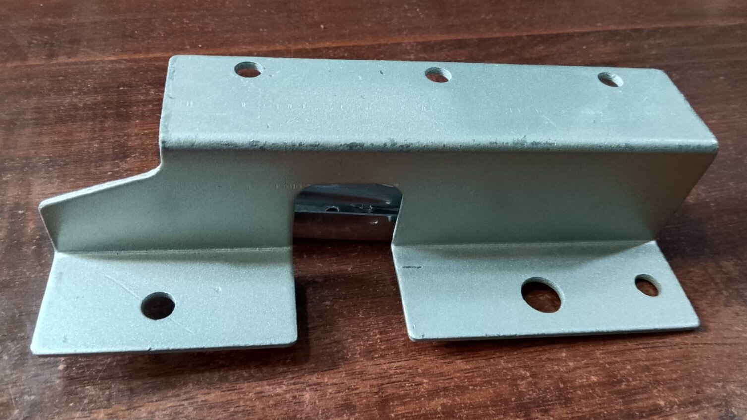 | Z Bracket 3 LTR Z Bracket 3 LTR View product → |
Frequently asked questions
What makes a Z bracket different from an angle bracket?
A Z bracket has two mounting faces separated by an offset, creating a stepped load path and clearance between planes. An angle bracket has one principal corner and does not provide the same built-in separation.
What information should a Z bracket drawing include?
Include overall dimensions, offset, material grade, thickness, bend angles, inside bend radius, hole size and position, tolerances, surface finish, quantity, and the required inspection points.
How do you verify a Z bracket will carry its working load?
Check the bracket orientation, load direction, unsupported length, material strength, thickness, bend region, fasteners, and mounting surface. Apply a stated safety factor and verify the critical failure mode, such as bending, tear-out, buckling, or bolt shear.
How should you evaluate a Z bracket manufacturer?
Compare drawing review, forming capability, material traceability, dimensional inspection, finish control, sample approval, batch consistency, packaging, and evidence that the supplier can meet your tolerances at the required volume.