A bracket that looks simple can fail because its holes miss by a few millimetres, its bend cracks, or its mounting face sees a load that the flat plate was never designed to carry. By the end, you will be able to identify the right bracket geometry, prepare measurable requirements, compare materials and finishes, and choose a manufacturing route that suits the application.
Key takeaways
- Match bracket geometry to load direction, clearance and fastening access.
- Measure installed dimensions from fixed datums, not worn or flexible surfaces.
- Check bolts, welds, anchors and connected parts across the complete load path.
- Specify material, coating, production method and acceptance checks before ordering.
Match the bracket geometry to its job
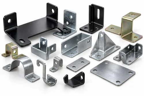
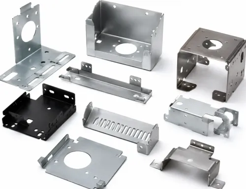
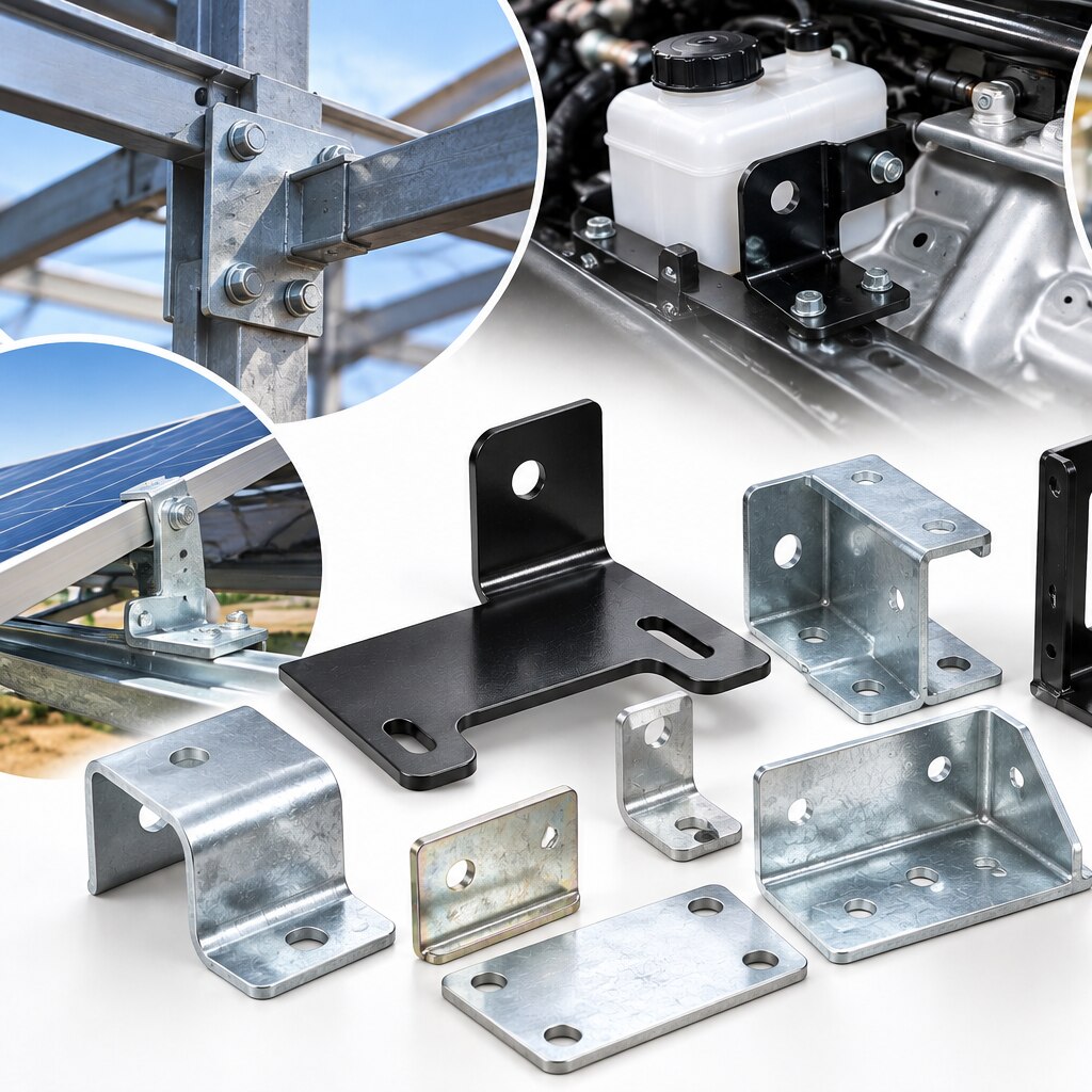
Choose the bracket geometry around the load, clearance and fastening direction, not around a catalogue label. Common industrial metal bracket uses include fuel-tank retention, machine guards, motor and pump mounts, electrical enclosures, panels, ducts, conveyors, vehicles, agricultural equipment and fixture frames.
- L brackets suit a simple 90-degree connection between two perpendicular faces, such as a panel or light guard. They are the wrong choice for a long unsupported leg carrying vibration unless a return flange or gusset stiffens it.
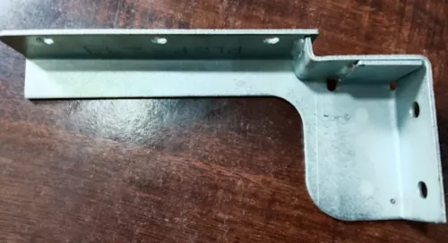
- Z brackets offset one mounting face from another, creating clearance around covers, ducts, wiring or a stepped panel. Do not use one where the offset introduces a twisting load that a direct L bracket would avoid.
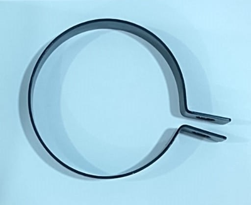
- Tank brackets spread a vessel’s load through a shaped saddle, strap or retaining flange. Use them for fuel-tank retention only after checking contact area, clamp movement and service access.
- Mounting plates provide a flat, hole-patterned interface for electrical equipment, small assemblies and motor and pump mounts. A plain plate becomes flexible when unsupported, so add ribs, folds or a separate gusset.
- Gussets reinforce an L or plate bracket at a loaded corner. They are unsuitable when they block tools, cable paths, inspection or drainage.
- Channel brackets resist bending and twisting along a longer span, making them useful for guards, conveyors and frames.
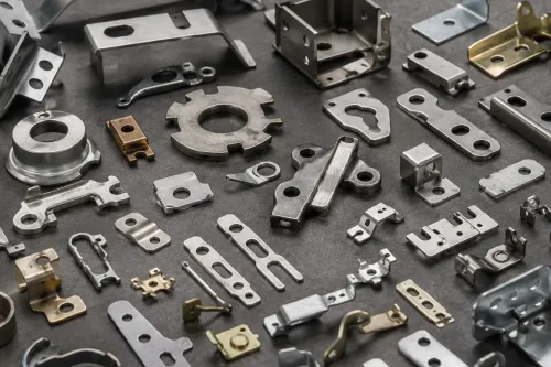
- Custom stamped or bent supports fit irregular clearances, multiple bends or high-volume assemblies where standard shapes create excess parts or fasteners.
Measure the installed part from fixed datums
Provide bracket dimensions from fixed mounting faces on the assembled equipment, so a replacement matches the actual load and attachment points rather than a nominal part name. Mark one primary datum face, one perpendicular locating face and, where needed, a third face to control orientation.
- Overall length and width of each flange
- Sheet thickness
- Bend angle and inside bend radius
- Hole diameter, slot length and hole-to-edge distance
- Hole centres measured from the selected datum faces
- Distance between bends and the height of each step
- Flatness, twist and any welded feature dimensions
- Clearance around the bolt, washer, nut and tool access
Measure the mating component too. Usable clearance depends on both hole patterns, bolt diameter, washer outside diameter and accumulated positional tolerance; an apparently correct hole can still block assembly, while an oversized hole can weaken bearing or lose repeatable location.
Record the installed angle and the clearance to nearby parts, cables or moving components. Holes near a bend can shift or distort during forming, so specify their position on the formed part; critical holes may need drilling, laser cutting or reaming after bending.
For approval, inspect the first article from the same functional datums and record thickness, bend angle, hole and slot positions, burr condition, flatness and any weld or coating measurements.
Check the complete load path, not just the plate strength
A bracket load rating is meaningful only when it states the load direction, support condition, lever arm, and allowable deflection.
Evaluate the complete path from the supported component through the bracket, fasteners, and mating structure; a plate that passes a static load check can still tear at a hole, yield at a bend, or loosen under shock and vibration.
1. Define every applied load, including weight, spring force, acceleration, impact, and side load. For a spring, use force at installed height and throughout the stroke, not free length alone. Include any change in line of action.
2. Calculate eccentricity. An offset force creates a secondary bending moment, M = F × e, which can control the bend, weld, or supporting frame even when direct tension looks low.
3. Check the joint, not just the plate. Verify bolt shear, plate bearing, net-section rupture, block shear, hole-edge bending, and clamp load. Treat a slot as a joint change: specify its length, width, orientation, washer or clamp plate, and permitted adjustment direction.
4. Set stiffness limits for movement, vibration, alignment, and fastener slip. Add a gusset, larger bend radius, or deeper section when deflection governs; simply increasing sheet thickness may add weight without fixing the load path.
5. Apply fatigue design to repeated actuation and vibration. Inspect weld toes, sharp inside corners, punched-hole edges, thickness steps, and unsupported flange transitions. Use generous radii, smooth transitions, a continuous load path, and specified weld finishing.
Have the supplier verify holes near bends after forming; critical positions may require drilling, laser cutting, or reaming on the formed part rather than trusting flat-blank dimensions. Record the calculated loads, cycles, safety factors, and deflection limit on the drawing.
Select material and corrosion protection for the environment
Choose the material and finish from moisture, chemicals, temperature and contact metals—not from the label “painted.” Use this comparison before ordering:
| Service | Material and protection | What to specify |
|---|---|---|
| Dry indoor enclosure | Carbon steel brackets with zinc electroplate or a documented paint system | Coating thickness, surface preparation and exposed-edge protection |
| Outdoor industrial exposure | Galvanized steel or a specified paint system over prepared steel | ISO 12944 corrosivity class, such as C3, C4 or C5, and required durability |
| Coastal or wet service | Stainless steel, selected by chloride exposure and strength needs | Grade, surface finish and fastener compatibility; 304 is not automatically suitable for every marine location |
| Chemical service | Stainless steel or coated steel proven compatible with the chemical, concentration and temperature | Chemical name, concentration, operating temperature and cleaning agents |
| Dissimilar-metal assembly | Match metals where possible; otherwise isolate the joint | Compatible washers, sealant or insulating barriers, plus a review of area ratio and coating damage |
Galvanized steel is not interchangeable with zinc electroplating. ISO 1461 covers hot-dip galvanizing and its coating can affect threads, small holes and fit; add vent and drain holes to hollow parts and state whether critical threads are tapped afterward.
Prevent aluminium bracket corrosion by separating aluminium from carbon steel, stainless steel or copper wherever moisture can enter. Review the joint after drilling or welding: damaged zinc or paint exposes a small anodic area, while welding adds distortion and removes local protection.
For high-strength steel, identify the grade before ordering zinc electroplate. ASTM B633-related hydrogen-embrittlement controls can require a specified relief bake, not merely the words “zinc plated.”
Choose the production method and define acceptance checks
Choose the production method by comparing tolerance, volume, geometry and the supplier’s inspection capability, not by unit price alone. Ask Shankar Spring And Coil Works which process controls your critical holes and bends, and whether the same supplier performs forming, deburring, welding and coating.
| Process | Strength | Check before ordering |
|---|---|---|
| Laser cutting | Flexible profiles, slots and low-to-medium quantities without dedicated tooling | Confirm heat-affected edges, burr limits and hole accuracy after bending |
| Punching and stamping | Fast repeat production with consistent tooling for higher quantities | Confirm tool wear control, rollover direction, burr height and press capacity |
| Press-brake bending | Flexible angles, short runs and formed channels or L brackets | Confirm inside bend radius, springback compensation and angle measurement method |
A hole near a bend can move or elongate when the flat blank is formed. If its position controls assembly fit, require formed-part datums and consider laser cutting, drilling or reaming after bending instead of accepting flat-blank dimensions.
Use a bracket inspection checklist for the first article and define pass/fail limits in the drawing or purchase order:
- Material certificate, sheet thickness, bend angle and inside radius
- Hole and slot position from mounting datums, plus diameter and clearance
- Flatness, twist, weld size and visible crack or distortion
- Burr direction or maximum height, with specified chamfer, radius or full removal
- Coating thickness and thread fit after finishing
Require the supplier to record these results on the first-article inspection report, not merely confirm that the part “matches the drawing.”
Related products
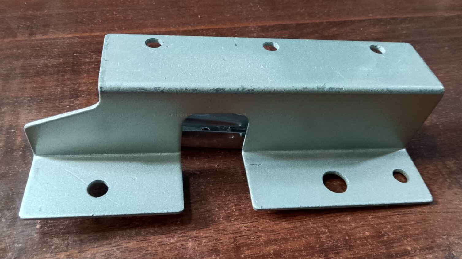 | Z Bracket 3 LTR Z Bracket 3 LTR View product → |
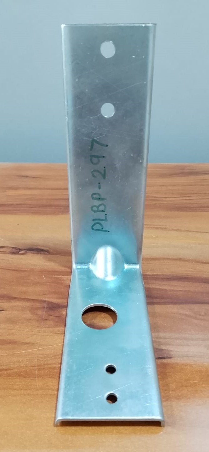 | L Bracket L Bracket L Bracket |
Frequently asked questions
How do you choose the right industrial metal bracket geometry?
Match the geometry to the load direction, available clearance, fastening direction and required stiffness. Consider angles, tabs, gussets, channels and formed shapes according to the installation.
How should you measure an installed bracket before ordering?
Measure from fixed datums such as machined edges, hole centres or enclosure faces. Record hole spacing, plate thickness, bend locations, offsets, clearances and fastening direction.
What should you check besides the bracket plate strength?
Check the complete load path, including bolts, welds, anchors, holes, connected panels, support members and the loads transferred into the equipment frame.
How do you select bracket material and corrosion protection?
Specify material and protection according to moisture, chemicals, temperature, outdoor exposure, galvanic contact and cleaning conditions. Compare carbon steel, stainless steel, aluminium and coated finishes for the actual environment.
What production and acceptance details belong on a bracket order?
Define whether the part is laser-cut, stamped, bent, welded or machined, then specify dimensions, tolerances, hole sizes, bend angles, weld requirements, surface finish and inspection checks.
Related products
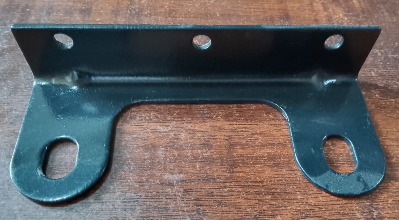 | Bracket (BIG) ) ( 3 LTR Tank) Bracket (BIG) ) ( 3 LTR Tank) View product → |
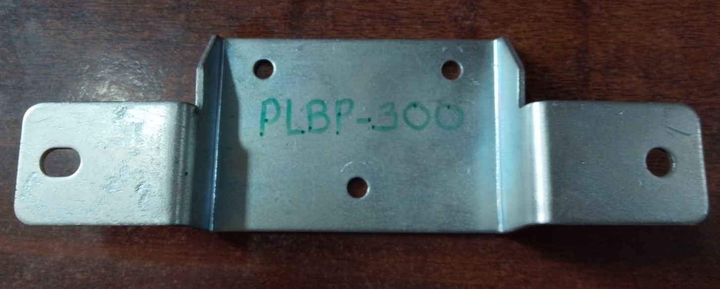 | 1 LTR Fuel Tank Bracket 1 LTR Fuel Tank Bracket View product → |
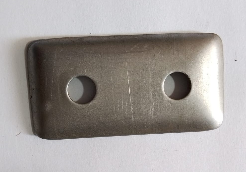 | Metal Plate Metal Plate View product → |
 | Bracket (DSK) Bracket (DSK) View product → |