A 1-litre label does not tell you whether a bracket will fit the tank, survive vibration, or protect the tank from damage. By checking the real load, mounting geometry, materials, isolation, clearances, and supplier controls, you can specify a support that remains secure in service rather than merely holding the tank during a static trial.
Key takeaways
- Measure tank mounting points before choosing a bracket.
- Verify load capacity under fuel, vibration and operating conditions.
- Specify corrosion protection, isolation material and bolt-retention controls.
- Approve samples against a documented inspection checklist before repeat orders.
Start with the Actual Tank, Load and Mounting Geometry
Confirm that a 1 LTR fuel tank bracket matches the actual tank dimensions and mounting points, then prove it carries the installed operating load. Capacity alone does not define fit or strength.
- Measure the tank’s length, width, height, mounting flange or saddle locations, hole diameter, hole spacing, orientation and nearby clearances. Compare these measurements with the bracket drawing and stated tolerances.
- Complete the tank load calculation using the empty tank, cap, fittings, hoses, trapped liquid and fuel. Fuel adds about 0.74–0.85 kg per litre, depending on fuel type and temperature.
- Multiply the supported mass by the machine’s specified or measured vertical, lateral and longitudinal acceleration factors. Include slosh-induced loads rather than checking only static weight.
- Trace the load path from the tank attachment into the chassis. Inspect bend radii, pierced holes, weld toes and section changes for stress concentration; a bracket that passes a static check can still crack under vibration.
- Assemble the actual tank, bracket, fasteners and liners for a first-article fit check. Verify that the tank stays clear of hot surfaces, exhaust components, sharp edges and likely impact zones.
Allow thermal expansion and production variation without forcing the tank into constant bending. One positively located mount paired with a slotted or compliant mount can provide movement control, but the slot must not permit vibration-driven tank movement.
Assess Structure, Fatigue and Corrosion Protection
A bracket can carry a static 1 LTR tank and still crack after repeated vibration. Check the load path from the tank attachment to the chassis, concentrating on bend radii, pierced holes, weld toes and abrupt section changes.
Request the bracket material grade, sheet thickness, bend radius and fatigue life evidence, not just a statement that the part is “heavy duty.” A thicker sheet may add mass without removing a resonance; shortening the unsupported span, increasing section stiffness or adding a correctly placed brace can work better.
| Material or finish | Structural value | Environmental risk |
|---|---|---|
| Named carbon-steel grade | Provides traceable strength and forming properties | Needs complete edge, hole and weld-zone protection |
| High-strength steel grade | Can increase stiffness without equal mass growth | Forming and bend-radius limits need confirmation |
| Stainless-steel grade | Resists humidity and fuel splash without a separate coating | Galvanic contact with an aluminium tank or frame needs control |
| Zinc-coated steel | Protects broad sheet surfaces economically | Cut edges, welds and damaged areas can corrode |
Check these production details before approval:
- Verify bend angle, hole diameter and spacing, flatness, bracket dimensions and tolerances; stack-up can change clamp load on a small tank.
- Ask for a vibration or resonance assessment covering operating speed and engine-order ranges, plus a fatigue-life basis for the actual load spectrum.
- For welded parts, define limits for undercut, incomplete fusion, porosity, distortion and weld-to-edge distance. A neat fillet proves little by itself.
Specify coating preparation and thickness for cut edges, holes, weld zones and trapped interfaces. Treat salt-spray hours as a coating comparison, not a field-life promise; include road salt, mud, humidity, fuel, cleaners and galvanic contact in the environment review.
Specify Isolation, Clearance and Fastener Control
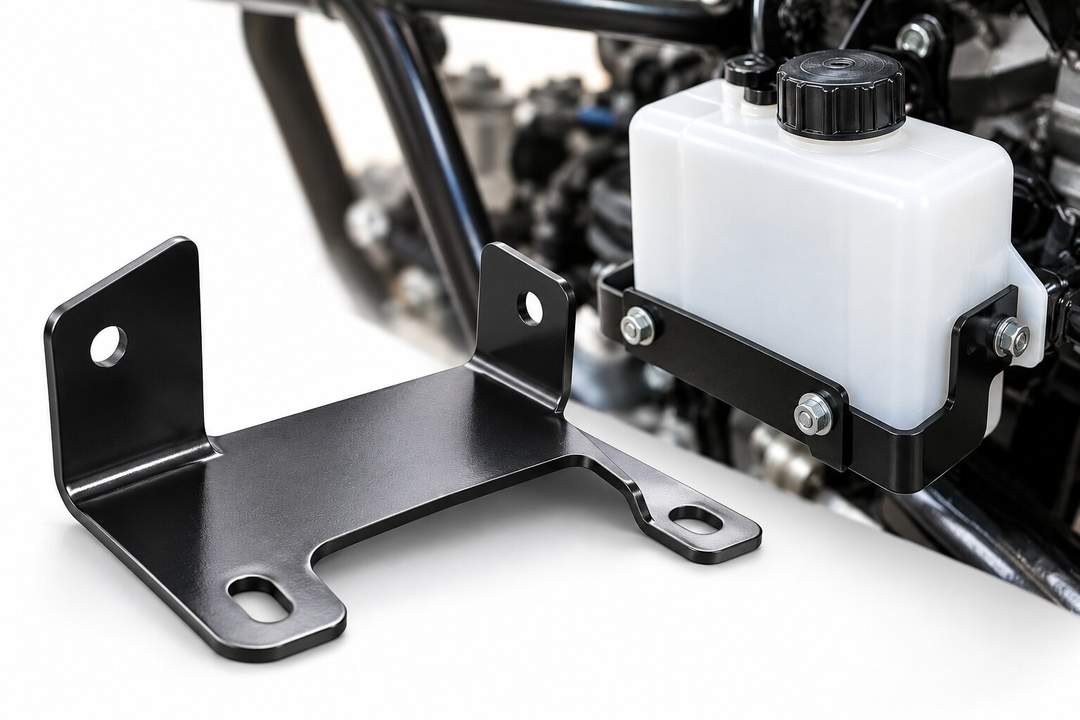
Do not let a metal bracket touch a polymer or thin-wall tank directly. Fit a fuel-compatible isolator or rubber liner across the full contact area to spread clamp pressure, reduce fretting and limit vibration transfer.
Keep the liner dry by providing a gap or drain path so spilled fuel, condensation and wash water cannot remain against the tank.
Perform a clearance check with the actual tank, fasteners and liner installed. Confirm that the bracket cannot contact the tank wall, seam, filler-neck region or any adjacent flexible or electrical route throughout the full vibration and tolerance range.
Do not use an unsupported tank area as a clamp point; tightening there can buckle or crack the tank.
Put these controls on the installation drawing:
- Specify the joint stack-up, tightening torque and clamp location, then verify that the liner hardness and contact width prevent local tank deformation.
- Use a locking nut, prevailing-torque nut or mechanically retained fastener rated for the vibration environment. A lock washer alone is not reliable control of preload loss.
- Allow thermal expansion with one positively located mount and one slotted or compliant mount. Restrain the tank so the slot cannot permit movement during vibration.
- Control bend angle, hole position, flatness, coating thickness and isolator hardness. Inspect the assembled bracket with the production tank before approval; tolerance stack-up can change clamp load substantially on a 1 LTR tank.
Choose the Bracket Form That Matches the Mounting Problem
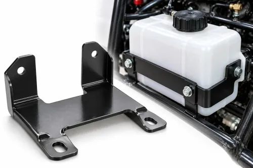
Choose a dedicated 1 LTR bracket when the tank has defined mounting points, limited installation space and a known support load. Its formed shape can maintain the specified clearance around the filler, hoses, exhaust and nearby structure without forcing the tank against a seam or unsupported wall.
| Option | What it means | When it applies |
|---|---|---|
| Dedicated tank bracket | Bracket shaped for the 1 LTR tank’s profile, mounting points and installation orientation | Prefer it when hole spacing, clamp width, clearance and load paths are known |
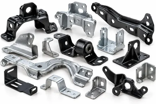
| L bracket | Two perpendicular legs with simple side or base mounting | Use for a straightforward right-angle attachment when the tank itself provides stable restraint |
| Z bracket | Offset legs that move the tank around an obstruction or create a different mounting plane | Use when clearance is needed behind, above or beside the tank; check the offset for vibration-induced bending |
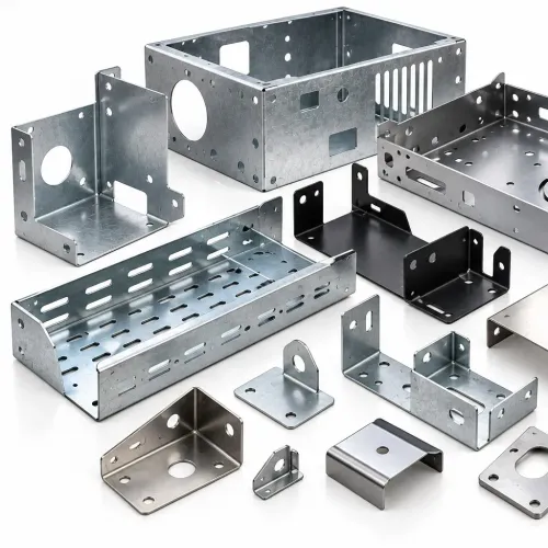
| Flat plate | A planar support with holes or straps added separately | Use only when the tank has adequate bearing support and the plate will not concentrate clamp force |
| Welded support | A bracket permanently joined to the machine frame | Use when a removable fastener joint cannot carry the measured vertical, lateral and longitudinal loads |
| 3 LTR tank bracket | Bracket sized for a larger tank and its different geometry | Reject it when its wider span or hole pattern leaves the 1 LTR tank loose or transfers force into weak areas |
Do not select by capacity alone: a larger bracket can shift the load path, while a small generic form can fatigue at its bends. Confirm the applicable fuel-system safety standard and keep the supported tank away from hot exhaust parts, sharp edges and impact zones.
Control Samples, Inspection and Repeat-Order Quality
Before approval, freeze the bracket drawing as the production reference. It must show material grade and thickness, hole diameter and spacing, bend angle, flatness, coating thickness, isolator hardness, weld details and tolerances; otherwise tolerance stack-up can change clamp load on a small tank.
1. Request a material certificate for each supplied grade and thickness, plus coating or plating records showing the specified finish and measured thickness. Record the batch number against the inspection report.
2. Require a first article inspection using the actual 1 LTR tank, fasteners and liners. The dimensional inspection must verify hole position, mounting height, bend angle, contact width, flatness and clearances, including freedom from chafing at hoses, vent lines, wiring and the tank wall.
3. Check the assembled bracket under tightening torque. Confirm that clamp force avoids tank seams, threaded inserts and unsupported filler-neck areas, and that the liner neither buckles the tank nor permits movement during vibration. Verify drainage gaps so fuel, condensation and wash water cannot remain trapped.
4. For welded parts, record acceptance criteria for undercut, incomplete fusion, porosity, distortion, weld-to-edge distance and weld size. A neat fillet alone does not prove fatigue strength.
Shankar Spring And Coil Works can support repeat supply only when the approved sample, revision-controlled bracket drawing and inspection limits travel together. Keep the signed first-article report as the control sample, then compare later lots against the same dimensions, finish, isolator hardness and weld criteria rather than approving them by appearance.
Reject an unapproved material, process or drawing change before installation.
Related product
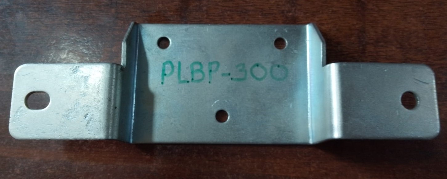 | 1 LTR Fuel Tank Bracket 1 LTR Fuel Tank Bracket View product → |
Frequently asked questions
What must you check before selecting a 1 LTR fuel tank bracket?
Measure the tank length, width, mounting-hole pattern, attachment points and available installation clearance. Check the bracket against the filled tank’s weight and operating loads, not capacity alone.
How do fatigue and corrosion affect fuel tank bracket selection?
Vibration and repeated load cycles can create fatigue cracks at bends, welds and bolt holes. Inspect the material, bend geometry and joints, then specify a corrosion treatment suitable for the tank’s environment.
What isolation and fastener details belong in the bracket specification?
Define rubber or polymer isolation, edge clearance, bolt size, washer arrangement, tightening torque and a method to prevent loosening. Confirm that the tank cannot contact a sharp bracket edge.
How can you control quality for samples and repeat orders?
Compare the sample with the approved drawing, material and surface-finish requirements. Record dimensions, hole positions, bend angles, coating condition and fastener fit, then use the same inspection points for repeat batches.