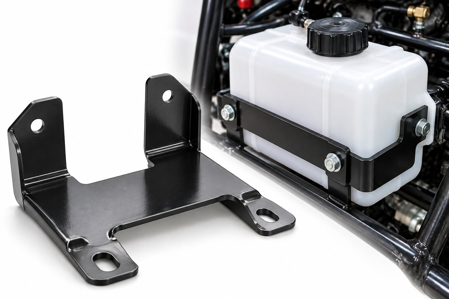
A 3 LTR fuel tank bracket must do more than hold a tank in place during assembly: it must control movement, carry changing loads and protect the tank from vibration damage. By the end, you will know how to measure the installation, compare bracket geometries, specify hardware and check whether the finished restraint is suitable for service.
Key takeaways
- Calculate full assembly mass, retained fuel and design acceleration loads.
- Match the bracket’s BIG or Z design to the tank and mounting space.
- Measure tank width, height, mounting points and clearance before ordering.
- Specify fastener grade, liner material, finish and service validation requirements.
How the bracket carries and restrains the fuel tank
A 3 LTR fuel tank bracket carries the tank’s full assembly mass, not merely its nominal 3-litre capacity. Fuel alone weighs roughly 2.1–2.6 kg, depending on the fuel; add the tank, fittings and retained contents, then apply the specified acceleration cases.
As the tank empties, its centre of gravity shifts, changing the forces at each mounting point.
A correctly fitted fuel tank restraint must stop:
- Tank movement during braking, vibration and impact.
- Rotation when the tank’s centre of gravity moves or the vehicle corners.
- Separation if an upward or sideways force lifts the tank from its supports.
- Local crushing or chafing caused by concentrated clamp pressure.
A partly filled tank creates a slosh load that a static full-tank pull test may not reproduce. The bracket therefore needs distributed contact, controlled preload and sufficient stiffness, while the tank wall, cap and vent system remain responsible for containing fuel.
Do not use the bracket to compensate for a weak tank, leaking fitting or loose fuel-cap seal.
Inspect the bolt holes, welds and contact profile as closely as the overall outline. A thin section can tear around a hole, a weld toe can crack under cyclic bending, and excessive torque can crush a plastic tank.
For vehicle use, compare the installation with 49 CFR 393.67, including secure attachment, heat clearance and protection from road damage.
Where the bracket fits and how BIG and Z designs differ
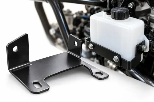
The load path runs from the tank wall or reinforced tank flange, through the contact pad or strap, into the bracket, and then through bolts or welds into the tank frame mounting. A wide contact area spreads force; a narrow edge can dent plastic, wear through a liner or start a crack.
Keep the bracket clear of the fuel hose, outlet and filler connection.
| Arrangement | Contact and load behaviour | Best fit |
|---|---|---|
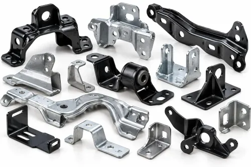
| BIG bracket | Broad face or longer support spreads load and offers more contact area; its mounting direction usually suits a direct tank-to-frame connection. | Tanks with a broad, accessible mounting face and limited local reinforcement. |
| Z bracket | Offset legs create a step between the tank and frame, helping bypass an edge, rib or fitting; the bend also changes the load direction. | Tanks needing stand-off, side mounting or clearance around hoses and frame members. |
| BIG bracket | A larger profile can provide more hole-position adjustment, but excessive unsupported span increases bending at the bolt holes. | Installations where the frame holes and tank contact points are close to the same plane. |
| Z bracket | The offset provides positional flexibility, but too little adjustment leaves bolt holes misaligned and too much offset increases leverage. | Installations where tank and frame holes sit at different heights or depths. |
Select by tank shape, not by the “3 LTR” capacity label. A round, curved or ribbed tank may need a formed BIG bracket; a boxed tank with a side outlet may suit a Z bracket.
Check that the mounting direction leaves fuel hose clearance throughout vibration and service movement, and confirm the contact surface supports the tank without touching only an edge.
What to measure before ordering the bracket
Measure the actual tank and installation envelope; “3 LTR” states capacity, not a guaranteed bracket shape, hole pattern or mounting geometry.
1. Record tank length, width and height at the maximum points, including seams, bosses and protective features. Note whether each dimension changes with a fitted cap, outlet or level sender.
2. Measure the curved-surface radius where the bracket will touch the tank. A flat contact on a curved wall concentrates force and can dent or abrade the tank.
3. Measure mounting-hole spacing centre to centre, hole diameter, hole-edge distance and the frame’s available hole locations. Record the bolt direction and the distance from each hole to the tank contact points.
4. Map every fitting, drain, filler neck, vent, fuel line and hose. Allow room for hose bend radius and clamp access; a bracket that touches a hose can cause leakage through vibration.
5. Check tank clearance around the full installation envelope: frame members, exhaust or heat sources, moving linkages and nearby wiring. Include clearance for vibration, thermal movement, tank expansion and bracket deflection.
6. Confirm cap removal, filling, draining, inspection and hose replacement without removing the bracket. Mark the service-access boundary on a sketch or photograph.
Send the drawing with measured tolerances, not nominal catalogue dimensions. Include the tank’s material, empty and full mass, and photographs of its mounting face so the contact profile and restraint travel can be matched correctly.
How to specify fasteners, liners and corrosion protection
Choose bolt diameter from shear, tension, hole-edge distance, bracket thickness and required clamp load—not from the 3 LTR capacity. Specify the bolt grade, such as ISO 898-1 property class 8.8 or an engineered alternative, along with its finish and torque range. Use flat washers with enough outside diameter to spread load.
Add a sleeve or torque-limiting spacer where tightening could crush a plastic tank.
| Choice | Selection point | Failure prevented |
|---|---|---|
| Flat washer | Size it for the slot or hole and bracket thickness | Pull-through and local deformation |
| Lock nut | Use a vibration-resistant type that suits the temperature and fuel environment | Fastener loosening |
| Threadlocker | Select a product rated for the joint temperature and chemical exposure | Thread back-out |
| Rubber tank liner | Specify fuel-compatible elastomer, thickness, retention and edge geometry | Tank wear, leakage and chafing |
State the actual fuel formulation and temperature range: petrol, diesel, ethanol-blended fuel, biodiesel and additives do not share compatibility. The rubber tank liner, adhesive, spring coating and corrosion finish must all tolerate that exposure.
Retain the liner so it cannot migrate, and taper or fold its edges away from the tank; a loose or sharp edge becomes a cutting point under vibration.
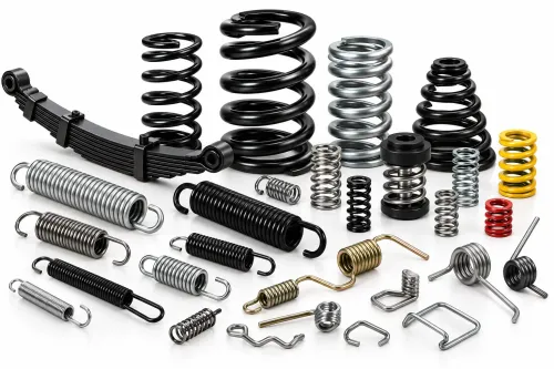
Protect bare steel after welding and forming, including burrs, weld spatter, lap joints and hidden coating holidays. Isolate plated steel from aluminium with a durable non-absorbent barrier, while preserving drainage so trapped water cannot start galvanic corrosion. Specify preload and travel for any spring restraint, not just free length or wire diameter.
How to validate the finished bracket for service
Approve the bracket only after the measured installation has passed a component and complete-system check. Use this procedure:
1. Record the spring free length, spring rate, installed preload, working deflection, available travel and solid height. Recheck preload after cycling; loss of contact or excessive compliance can let the tank strike its support.
2. Run fatigue and vibration testing with the tank empty, partly filled and full. Check for resonance near engine, fuel-pump and road-vibration frequencies, then inspect for cracked metal, permanent deformation and loosening. Ultimate pull strength alone will not reveal a high-cycle failure.
3. Inspect every weld for incomplete fusion, undercut, porosity, sharp projections and cracking. Use dye-penetrant or another suitable non-destructive test where the joint carries a critical load.
4. Verify coating coverage on edges, weld toes and contact faces. Confirm that the liner, adhesive, coating and any exposed spring finish suit the actual petrol, diesel, ethanol blend, biodiesel or additives and the specified temperature range.
5. Match the bracket, spring and fasteners to material certificates, drawing revision, inspection results and batch or heat numbers. Traceability must remain intact from incoming material through final inspection.
6. Validate the complete fuel system, including the tank, hoses, fittings, filler neck and surrounding structure. FMVSS No. 301 addresses post-crash fuel-system integrity and fuel spillage; a bracket bench test does not prove compliance.
Shankar Spring And Coil Works can convert measured clearances and loads into a controlled specification covering spring rate, installed preload, tolerances, weld details, coating and inspection records.
Related products
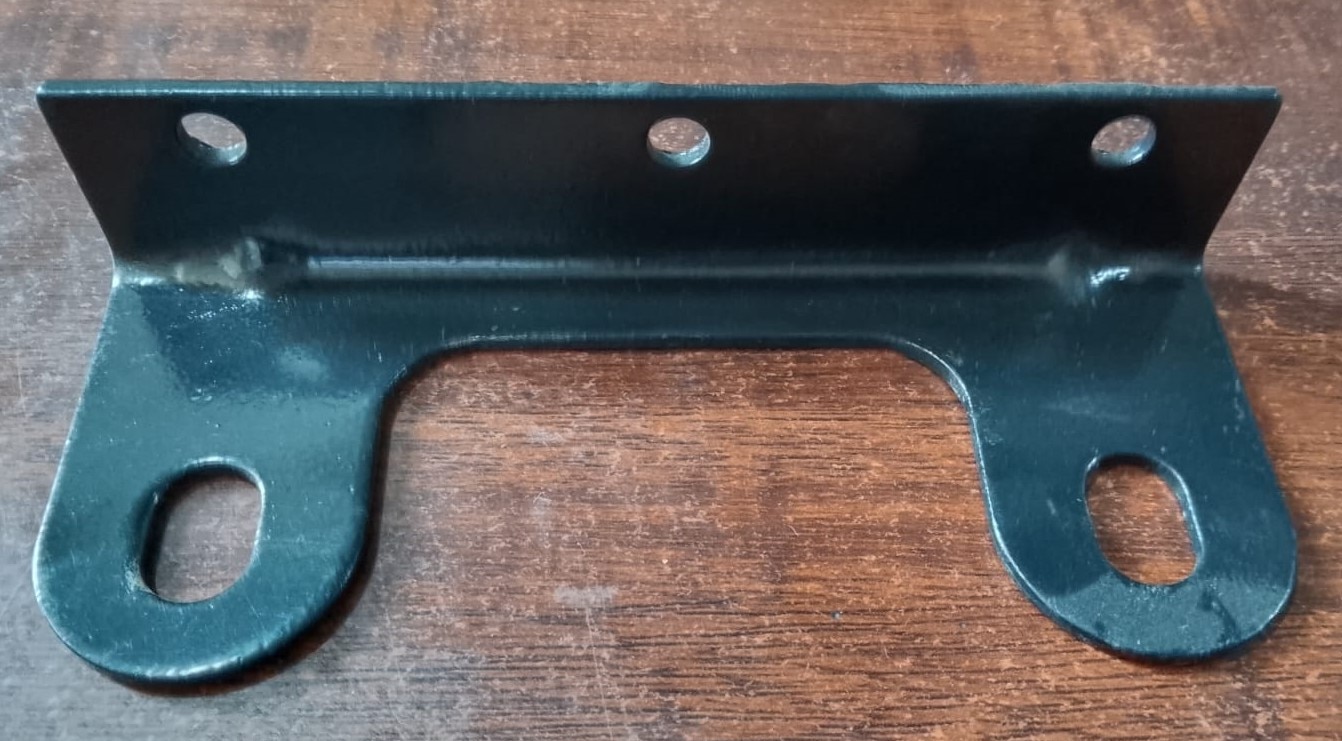 | Bracket (BIG) ) ( 3 LTR Tank) Bracket (BIG) ) ( 3 LTR Tank) View product → |
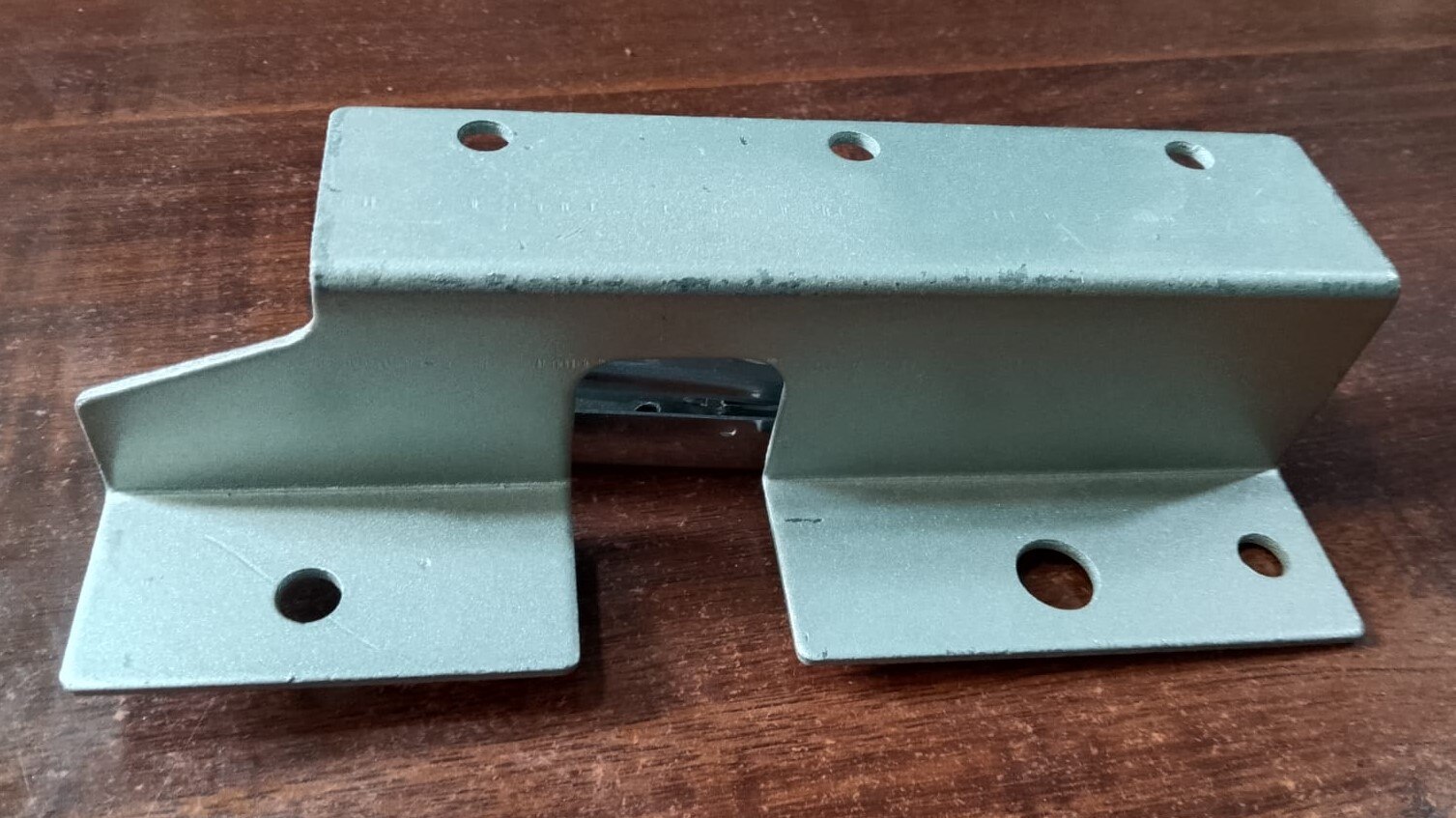 | Z Bracket 3 LTR Z Bracket 3 LTR View product → |
Frequently asked questions
How does a 3 LTR fuel tank bracket carry and restrain the tank?
It supports the tank, fittings and retained fuel while resisting movement from vehicle or equipment acceleration. Check the full assembly mass and specified load cases rather than sizing for fuel capacity alone.
How do BIG and Z fuel tank bracket designs differ?
BIG and Z designs use different formed profiles and mounting geometry. Select the design that matches the tank shape, frame interface, available clearance and load path.
What should you measure before ordering a 3 LTR fuel tank bracket?
Measure tank length, width, height, mounting-hole locations, frame spacing, fastener access and clearance from heat sources, moving parts and nearby components.
How should you specify fasteners, liners and corrosion protection?
State the fastener size and grade, liner material and thickness, surface finish, service environment and galvanic-contact limits. Ensure the liner grips the tank without cutting or crushing it.
How do you validate a finished fuel tank bracket for service?
Inspect dimensions, welds, holes, finish and liner placement, then confirm fit and fastener torque. Test the assembly against the specified static and acceleration loads without tank damage or excessive movement.